
I spent a few evenings recently trying to add a Shelly 1 Gen 4 to my existing wired doorbell so I could integrate the old-school indoor chime into my modern home automation setup, without losing the way the physical doorbell already worked. This post is the writeup of what I got wrong the first time, what actually works, and the final wiring I ended up with — hopefully it saves the next person some time.
The thing that actually got me across the finish line was this thread I posted on r/ShellyUSA, and specifically a one-sentence reply from u/DreadVenomous that reframed the whole problem. If you’re in the same spot, go read that thread — the rest of this post is just me showing my work.
What I actually wanted
Concretely, here’s what I was trying to end up with:
- The physical, lighted doorbell button at my front door should still ring the indoor chime, exactly like it always has. No behavior change from anyone’s perspective standing on the porch.
- When someone rings my new UniFi Doorbell Lite, the old indoor chime should also ring — so I don’t have to replace or duplicate any hardware inside the house just to hear the new doorbell.
- The Shelly should be able to see the physical button press, too, so I can get push notifications and trigger other automations when the old-school button is used — not just when the UniFi doorbell is used.
Basically: unify two doorbells into one chime, keep the physical button working, and get event notifications from both. All three of these things now work, and the trick — as it usually is with this kind of thing — turned out to be one specific detail about how the Shelly wants its inputs wired.
An aside: I wasted an entire Saturday trusting an LLM with wiring advice
Before I got to Reddit, I spent an entire Saturday going back and forth with Google Gemini trying to figure this out. Across roughly ten different wiring scenarios, Gemini kept insisting — confidently, in detail, with diagrams — that if I simply shorted the two terminals on the transformer in the garage, the indoor chime would ring. It would explain why, walk me through how, and then when it didn’t work it would apologize and propose the next variation of essentially the same wrong idea.
It was never true. Not once. Shorting the transformer output doesn’t ring a chime — it just makes an angry transformer. But because the answers sounded right and were delivered with such confidence, I burned a whole day of a weekend chasing them before I finally gave up and posted on Reddit, where an actual human with actual experience gave me the correct answer in one sentence.
Lesson learned: maybe don’t take electrical wiring advice from AI/LLMs yet. Especially the confidently-wrong kind. There is a real difference between “language model that’s read a lot of forum posts about doorbells” and “person who has actually wired one.”
Anyway. On to the thing that actually worked.
What I started with
A pretty standard old-school wired doorbell setup:
- A 16V AC transformer in the garage.
- An indoor chime (“gong”) box on a wall inside the house.
- An outdoor lighted doorbell button at the front door.
- Two pairs of red/green wires landing on the transformer — one pair going to the doorbell/chime loop, and one pair going to a long-abandoned security system.
I had a 12V DC wall-wart adapter on hand to power the Shelly, and the Shelly itself was already provisioned and talking to my phone. What I couldn’t figure out was how to wire the Shelly into the doorbell circuit without breaking the physical button.
What I tried first (and why it didn’t work)
Following Gemini’s guidance, my first instinct was to do all of this at the transformer in the garage, since that’s where all the wires converged. I wired the Shelly’s I (Input) terminal to the top screw of the transformer (the red side) and the O (Output) terminal to the bottom screw (the green side), figuring the Shelly would just close a contact across the transformer output whenever I activated it.
What actually happened: when I toggled the Shelly, the transformer emitted an angry hum and the chime never fired. In hindsight this is obvious — I was effectively shorting the transformer’s output through the Shelly’s dry-contact relay instead of switching the chime coil in series with the AC supply. The transformer did not enjoy that.
The right approach
u/DreadVenomous on r/ShellyUSA nailed it in one sentence:
You have to convert the doorbell to 12V DC and connect that to the SW terminal on Shelly 1. Then switch the 16V AC chime using the I and O terminals.
In other words:
- The Shelly needs to be in series with the chime coil, not across the transformer.
IandObecome a switch on the 16V AC loop that fires the chime. - The physical doorbell button should be a low-voltage dry-contact input into the Shelly’s
SWterminal, not part of the AC chime loop directly. That way the Shelly sees the button press and can be configured to fire the chime (and do anything else you want) in response. - To feed the button as a dry contact into
SW, you need low-voltage DC — so you convert 16V AC → 12V DC and use that to both power the Shelly and provide the button-sense voltage.
The key detail that took me a while to internalize: the “wet” side of the Shelly circuit — the 12V DC power coming in, and the switch wire coming in from the physical button — has to be the same voltage. In practice that meant running 12V DC out to the physical doorbell button instead of the 16V AC that used to power it. Once I did that, everything downstream just worked.
The rough diagram Dread and I sketched out looked like this, using a standalone 12V DC wall adapter to power the Shelly:
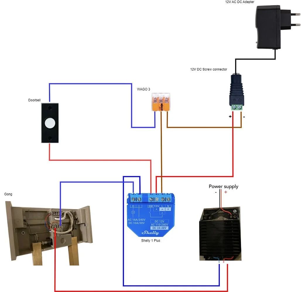
Once I could see the topology, the “do it at the chime, not at the transformer” advice made total sense — the chime box already has both the 16V AC loop and the button return landing in it, so it’s the natural spot to splice in the Shelly.
What I actually built
Rather than run a separate 12V DC wall adapter into the chime box, I picked up a small 16V AC → 12V DC converter and drove it directly off the existing 16V AC transformer. That kept the whole install inside the doorbell chime box with no extra outlet, no extra cable runs, and nothing new for anyone to notice.
Here’s the final wiring diagram I went with:
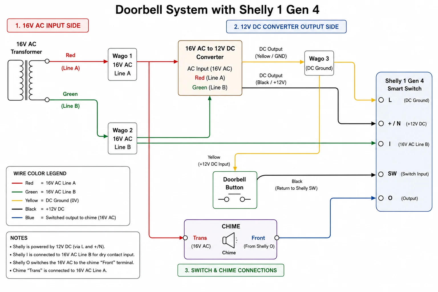
A small AI plot twist: after everything above, I did still want a clean diagram to document what I’d built. I spent about two hours trying to get Google Gemini to draw it and it never came even remotely close — wrong terminals, wrong topology, wires going to nowhere, the whole mess. Out of frustration I gave the same task to ChatGPT, and three prompts later it produced the diagram you see above — accurate, labeled correctly, and exactly what I actually wired. So: don’t trust LLMs to design your electrical wiring, but at least one of them can do a very nice job of drawing the wiring you already got right from a human.
The short version of what’s happening:
- 16V AC Line A (red) goes through a Wago into the AC input of the AC→DC converter, and also into the chime’s
Transterminal. - 16V AC Line B (green) goes through a Wago into the other side of the AC→DC converter, and also into the Shelly’s
Iterminal. - The 12V DC output of the converter powers the Shelly via
L(ground) and+/N(+12V), and also provides the +12V that runs out through the doorbell button and back into the Shelly’sSWterminal. Pressing the button just closes that dry-contact loop; the Shelly sees the press and reacts. - The Shelly’s
Oterminal is the switched 16V AC output that fires the chime’sFrontcoil. Whether the trigger came from the physical button (viaSW) or from the Shelly app / an automation, the chime rings the same way.
Notes worth calling out:
- The Shelly is powered by 12V DC via
Land+/N. - Shelly
Iis connected to 16V AC Line B for the dry-contact input side of the chime relay. - Shelly
Oswitches 16V AC out to the chime’sFrontterminal. - The chime’s
Transterminal stays on 16V AC Line A the way it always was. - The physical doorbell button is now on a 12V DC loop, not on 16V AC.
How it turned out
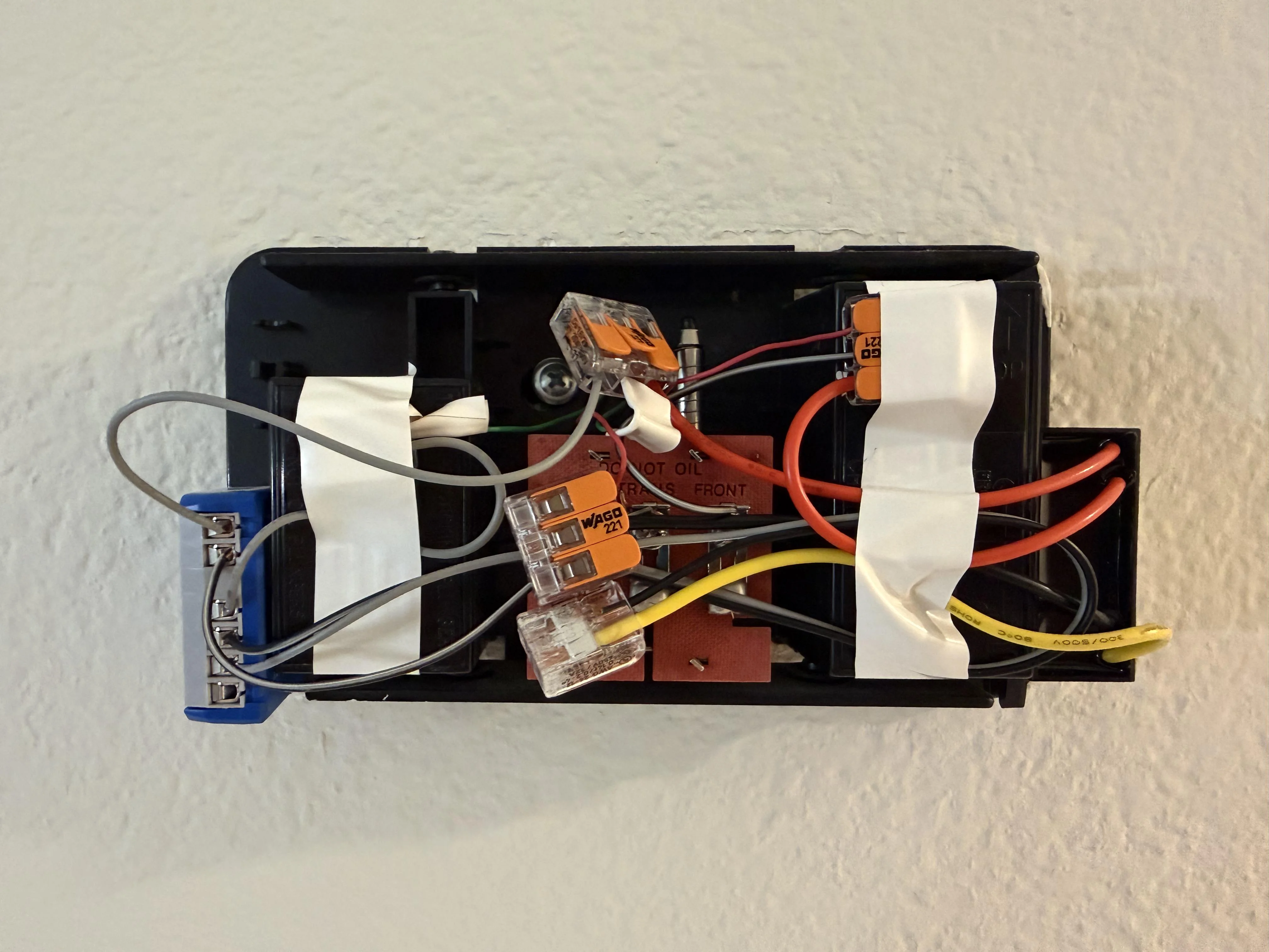
Everything got crammed into the existing chime box — the AC→DC converter, the Shelly, and three Wagos to keep the splices tidy. The doorbell chime cover still fits over the whole thing without issue. The wiring is a little chaotic in this picture and I’ll clean it up on the next pass, but it works perfectly.
Wiring the UniFi Doorbell Lite into the chime
Once the wiring was sorted, everything I wanted from the intro just fell into place. On the Shelly side:
- Configured the Shelly’s output as a momentary button with a 0.4 second automatic release, so a “press” briefly closes the AC loop through
I/Oand fires the chime the same way a physical button press does — no need to send a second command to turn it back off. - Gave the Shelly a static IP via a DHCP reservation on my UniFi UDM Pro, so I have a stable address to hit from other systems.
Then in UniFi Protect, I added a webhook alert on the UniFi Doorbell Lite’s “someone rang the doorbell” event pointed at the Shelly’s local HTTP endpoint. Now when a visitor pushes the UniFi doorbell, Protect fires the webhook, the Shelly closes its relay for 0.4 seconds, and the old indoor chime rings exactly like it would if a person had pushed the physical button on the wall. Meanwhile the physical button still works entirely on its own, and the Shelly can see and report on both kinds of events. All three original goals, done.
If you’re staring at your own doorbell transformer trying to figure this out: don’t do it at the transformer. Do it at the chime, convert down to 12V DC, put the Shelly in series with the chime coil on the AC side, and feed the button into SW as a dry contact on the same 12V DC. And whatever you do, read the Reddit thread before you ask an LLM. Good luck!